As a starting point, the principle of this manipulation technique is tested with the simplest setup. A single straight conducting line with two contact pads at both ends is patterned with optical lithography. Above the conducting line, a drop of water with magnetic markers is placed. A current through the line creates a magnetic gradient field, that magnetises the superparamagnetic markers, aligns them to the magnetic field and pulls the markers to the conducting line. Figure 3.6 shows 5 selected images of the video of this simple experiment.
|
[0sec] ![\includegraphics[width=.3\textwidth]{Bilder/Leiter1}](img149.png) [10sec]
[10sec]![\includegraphics[width=.3\textwidth]{Bilder/Leiter2}](img150.png) [20sec]
[20sec]![\includegraphics[width=.3\textwidth]{Bilder/Leiter3}](img151.png) [30sec]
[30sec]![\includegraphics[width=.3\textwidth]{Bilder/Leiter4}](img152.png) [33sec]
[33sec]![\includegraphics[width=.3\textwidth]{Bilder/Leiter5}](img153.png)
|
A constant current of 5mA is already enough to attract a magnetic
marker that is about 33![]() m away. Without the magnetic field, the marker
just follows the brownian motion [78], but with the
magnetic gradient field it slowly moves towards the conducting line. The
marker accelerates towards the conducting line until it reaches the
local field maxima on top of the line. Before it reaches the conducting
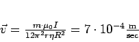
line, the maximum velocity of the bead is about 6
m away. Without the magnetic field, the marker
just follows the brownian motion [78], but with the
magnetic gradient field it slowly moves towards the conducting line. The
marker accelerates towards the conducting line until it reaches the
local field maxima on top of the line. Before it reaches the conducting
line, the maximum velocity of the bead is about 6![]() m/sec.
m/sec.
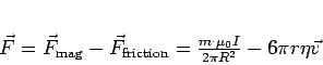
In order to describe the forces that act on the magnetic marker, the
friction of the marker in the fluid (STOKES' law)
has to be subtracted from the magnetic force (see equation
1.10 on page ![[*]](crossref.png) ):
):
This initial experiment proves that in principle the manipulation works well. Several more examples for particle manipulation are following.