The electron tunneling effect is a purely quantum-mechanical effect and first theoretical studies were published in the early 1930s [117]. Although the TMR effect was discovered early in 1975 [73], it took two more decades, and the discovery of the Giant Magneto Resistance (GMR) [5,12], until the interest in the TMR effect grew quickly.
|
[Wave function ![\includegraphics[width=.55\textwidth]{Bilder/tunnel-wave}](img90.png) [Sketch of a M/I/M model with an applied bias
Voltage
[Sketch of a M/I/M model with an applied bias
Voltage ![\includegraphics[width=.35\textwidth]{Bilder/tunneling-barrier}](img91.png)
|
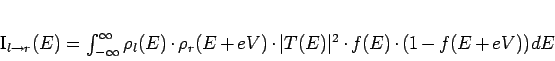
Figure 1.13(a) shows the wave function ![]() of two
electrodes separated by an insulating barrier. Although classically
forbidden, a part of the wave function continues beyond the barrier.
Because the wave function has to be continuous, it decays exponentially
within the insulator. If the barrier is too thick, the wave function
vanishes beyond the barrier.
of two
electrodes separated by an insulating barrier. Although classically
forbidden, a part of the wave function continues beyond the barrier.
Because the wave function has to be continuous, it decays exponentially
within the insulator. If the barrier is too thick, the wave function
vanishes beyond the barrier.
In a MTJ the electrons tunnel only through thin insulating barriers
(only a few nanometers thick) and, therefore, a reasonable tunneling
current can be measured. Those metal/insulator/metal systems are mostly
analysed by measuring the current/voltage (![]() ) characteristic.
Figure 1.13(b) shows a sketch of such a system. The
Fermi-levels
) characteristic.
Figure 1.13(b) shows a sketch of such a system. The
Fermi-levels ![]() of the two metals are shifted because of the
applied bias Voltage
of the two metals are shifted because of the
applied bias Voltage ![]() . The tunneling through an insulator mainly
depends on the the density of states (DOS) in the left and right
electrode. The current from the left to the right electrode can be
written as:
. The tunneling through an insulator mainly
depends on the the density of states (DOS) in the left and right
electrode. The current from the left to the right electrode can be
written as:
While the easiest way to get the properties of the barrier is the
Simmons-fit [116], which assumes a rectangularly shaped
barrier, in this thesis the more elaborate BRINKMAN-fit is used.
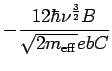
BRINKMAN et al. [17] used the WKB-approximation to
numerically calculate the transmission probability ![]() for a
trapezoidally shaped barrier. The first terms of the WKB-approximation give
for the conductance:
for a
trapezoidally shaped barrier. The first terms of the WKB-approximation give
for the conductance:
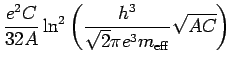
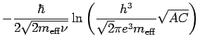
![]() . So when the conductance is
measured, the barrier parameters can be obtained by fitting the
parameters A,B and C:
. So when the conductance is
measured, the barrier parameters can be obtained by fitting the
parameters A,B and C: